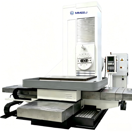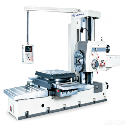
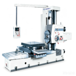
Planing Table Boring Machine
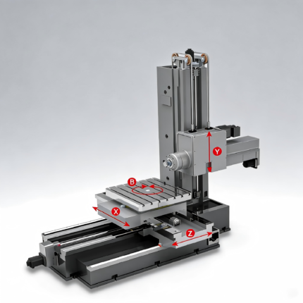
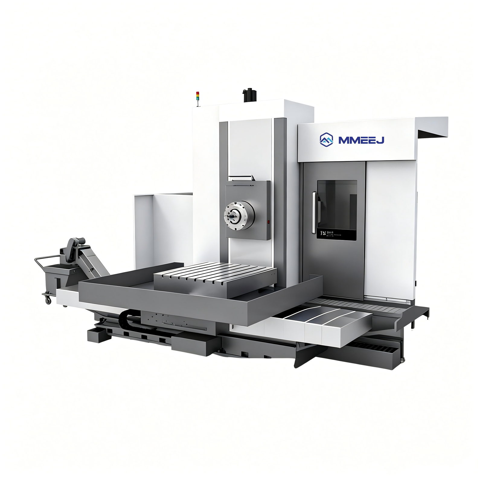
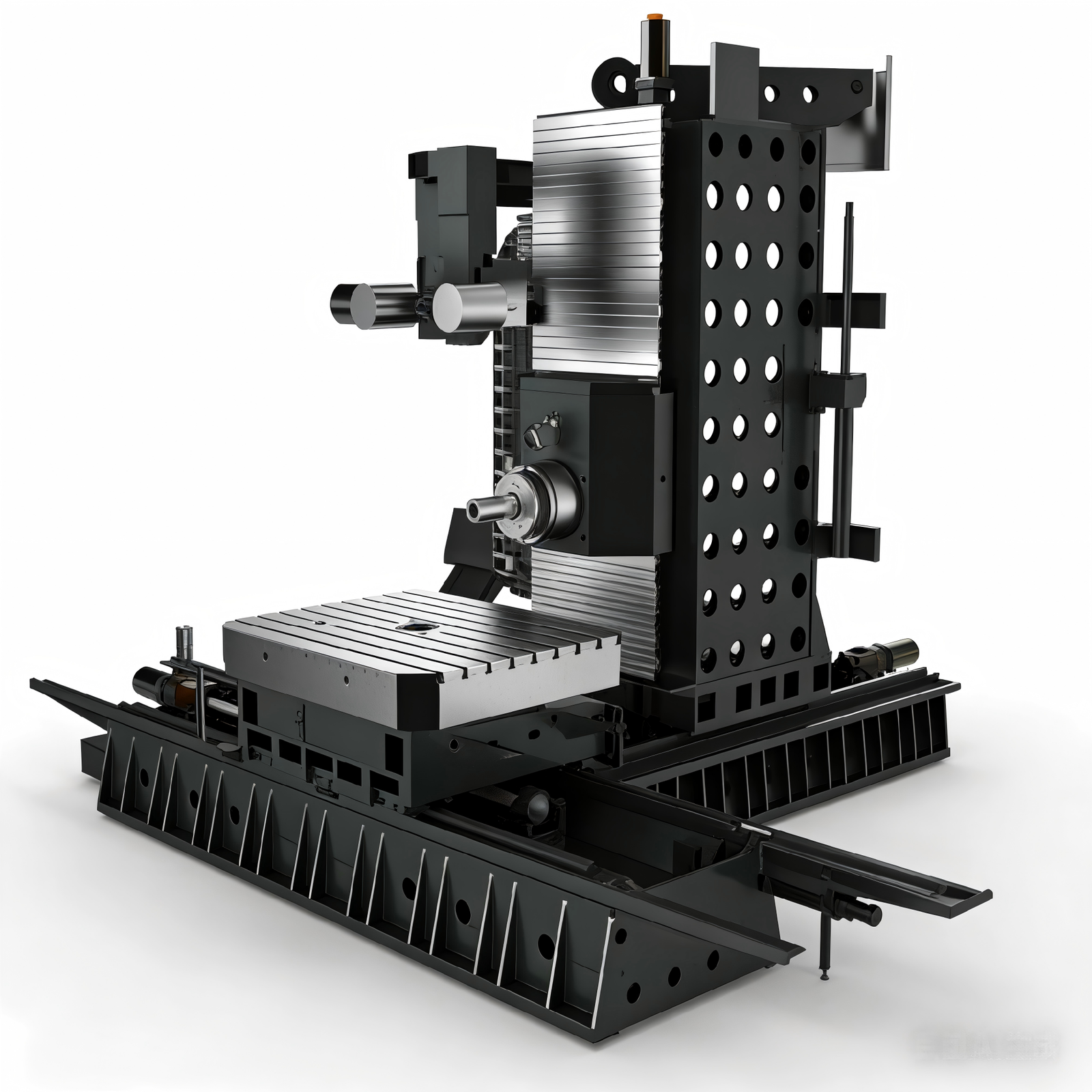
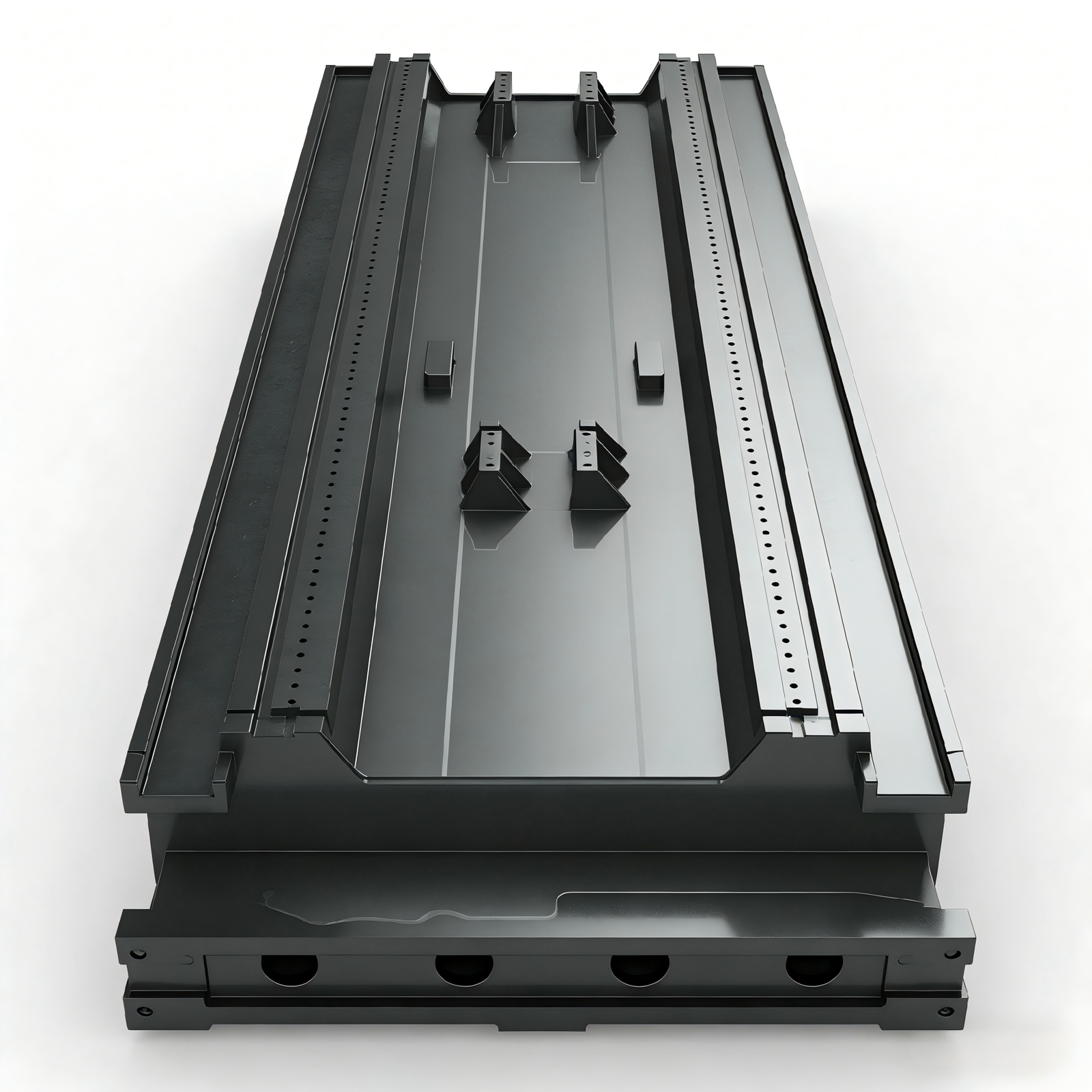
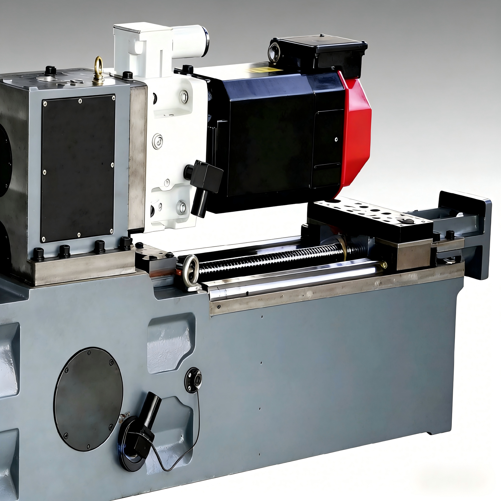
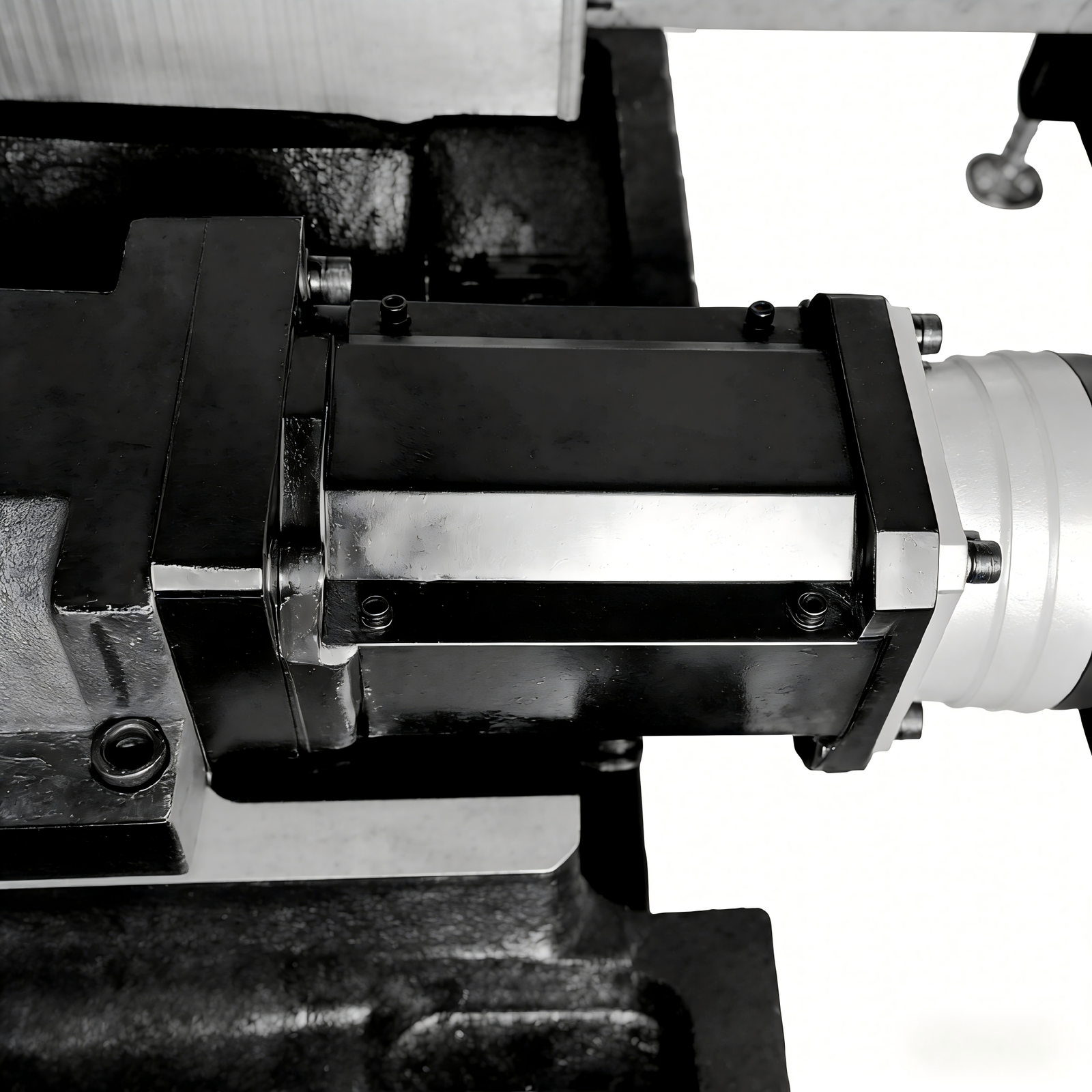
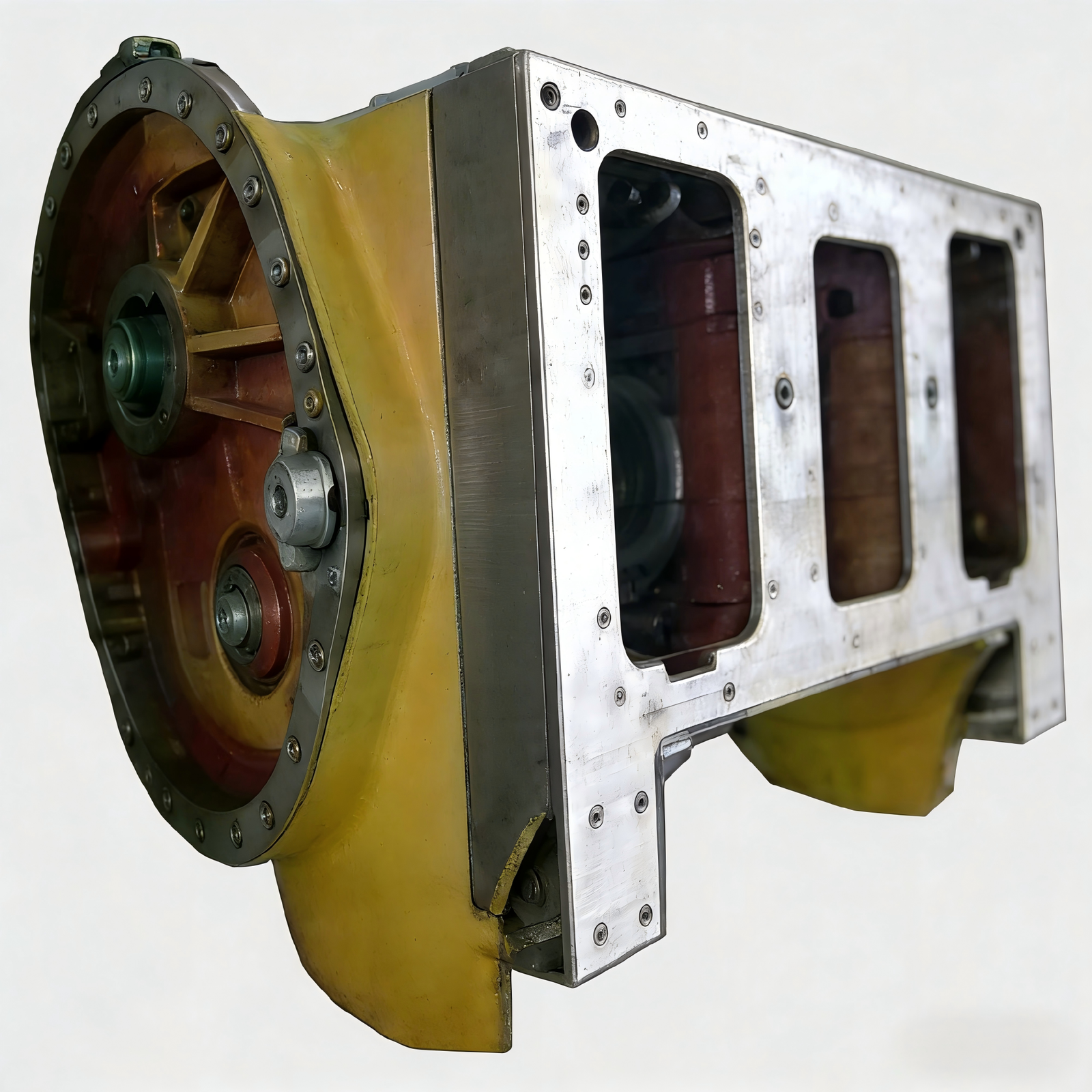
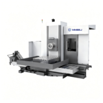
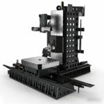
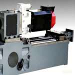
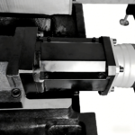
The machine tool is of T-shape layout, single column and lateeralsuspension headstock structure. The workbench and slidee carriage move along transverse bed
guiderail (X-axis coordinate), the column is fixed on slide carriage and mg longitudinal bed guiderail (Z-axis coordinate), headstock moves vertical
column guiderail (Y-axis coordinate); the product is of T-shape bed layouit. CNC workbench features 360° rotation (B coordinate), and spindle(boringshaft) moves in milling shaft (W-axis coordinate).
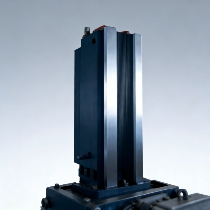
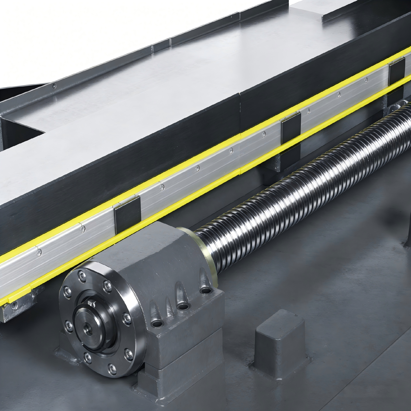
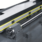
X-axis, Y-axis and Z-axis adopt integralsteelguiderail. The hardness after quenching and finish machining can reach HRC60 = 2.The guiderail and
polytetrafluoroethylene sheet form guiderail pair in frontal direction, anthe lateral direction is roller guide. The product features high accuracy,nall friction and
high accuracy maintenance. The circular guiderail of workbench rotationadopts casting iron-polytetrafluoroethylene guiderail pair. The product isinstalled with
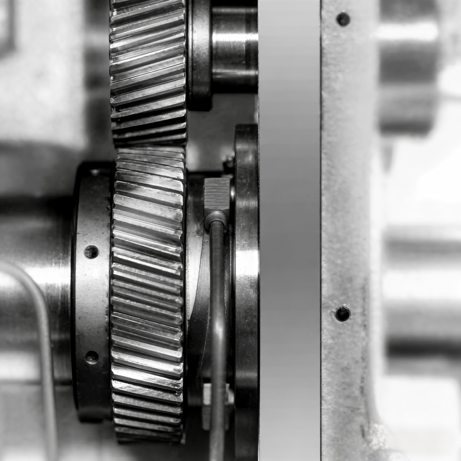
imported thrust bearing to release load,adopts double-wornn mechanism to eliminate clearance, and features stable motion and high positioning accuracy.
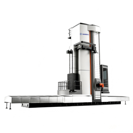
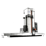
Floor-type Boring Machine
| Technical parameters | ||||||||
| item | unit | TK(H)6511B | TK(H)P6511B | TK(H)6513 | TK(H)P65113 | TK(H)6516 | TK(H)P6516 | |
| Workbench size | mm | 1000×1250 1250×1400 | 1000×1250 1250×1400 | 1400×1600 1600×1800 2000×2000 | 1400×1600 1600×1800 2000×2000 | 1600×1800 A:2000×2500 B:2500×3000 | 1600×1800 A:2000×2500 B:2500×3000 | |
| Maximum allowable load | T | 5 | 5 | 10 | 10 | 10, A:20, B:30 | 10, A:20, B:30 | |
| Spindle diameter | mm | φ120 | φ110 | φ130 | φ130 | φ160 | φ160 | |
| Facing head diameter | mm | / | φ630 | / | φ730 | / | φ900 | |
| Spindle rotary speed | r/min | 10-2500 | 10-2000 | 10-2000 | 10-2000 | 10-1500 | 10-1500 | |
| Tool handle specification | JT50/BT50 | JT50/BT50 | JT50/BT50 | JT50/BT50 | JT50/BT50 | JT50/BT50 | ||
| Main motor power | KW | 19.5/23.4 | 19.5/23.4 | 25/30 | 25/30 | 41/49.2 | 41/49.2 | |
| Maximum spindle torque | Nm | 1300/1600 | 1300/1600 | 2500/3000 | 2500/3000 | 3300/4000 | 3300/4000 | |
| X-axis stroke | mm | 2000/2500/3000 | 2000/2500/3000 | 2000/3000/4000 | 2000/3000/4000 | 3000/3500/4000 | 3000/3500/4000 | |
| Y-axis stroke | mm | 1500/2000 | 1500/2000 | 1600/2000 2500/3000 | 1600/2000 2500/3000 | 2000/2500/3000 | 2000/2500/3000 | |
| Z-axis stroke | mm | 1200/2000 | 1200/2000 | 1600/2000 | 1600/2000 | 2000 | 2000 | |
| W-axis stroke | mm | 550 | 550 | 800 | 800 | 1000 | 1000 | |
| U-axis stroke | mm | / | 140 | / | 200 | / | 330 | |
| Feed speed | X,Y,Z | mmmmin | 1-6000 | 1-6000 | 1-000 | 1-000 | 1-6000 | 1-6000 |
| W | mmmmin | 1-2000 | 1-2000 | 1-3000 | 1-3000 | 1-3000 | 1-3000 | |
| U | mmmin | / | 1-1000 | / | 1-3000 | / | 1-3000 | |
| B | 0-1.5 | 0-1.5 | 0-1 | 0-1 | 0-1 | 0-1 | ||
| Fast moving peed | X,Y,Z | m/min | 10 | 10 | 10 | 10 | 10 | 10 |
| W | m/min | 24 | 24 | 3 | 3 | 3 | 3 | |
| U | m/min | / | 24 | / | 3 | / | 3 | |
| B | r/min | 2.5 | 2.5 | 1 | 1 | 1 | 1 | |
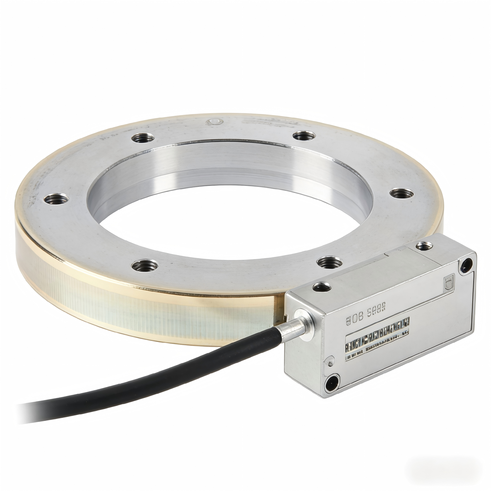
| Positioning accuracy Standard:JB/T4373.1-2019 | X,Y,Z | mm | X:0.018/0.015(Grating) Y:0.018/0.015(Grating) Z:0.016/0.013(Grating) | X:0.018/0.015(Grating) Y:0.018/0.015(Grating) Z:0.016/0.013(Grating) | X:0.018/0.015(Grating) Y:0.018/0.015(Grating) Z:0.016/0.013(Grating) | X:0.018/0.015(Grating) Y:0.018/0.015(Grating) Z:0.016/0.013(Grating) | X:0.028/0.022(Grating) Y:0.02/0.016(Grating) Z:0.02/0.016(Grating) | X:0.028/0.022(Grating) Y:0.02/0.016(Grating) Z:0.02/0.016(Grating) |
| W | mm | 0.016 | 0.016 | 0.016 | 0.016 | 0.018 | 0.018 | |
| U | mm | / | 0.032 | / | 0.032 | / | 0.032 | |
| B | " | 8,4x90°:6 | 8,4x90°:6 | 8,4x90°:6 | 8,4x90°:6 | 8,4x90°:6 | 8,4x90°:6 | |
| Repeat Positioning accuracy Standard:JB/T4373.1-2019 | X,Y,Z | mm | 0.01 | 0.01 | 0.012 | 0.012 | 0.013 | 0.013 |
| W | mm | 0.014 | 0.014 | 0.014 | 0.014 | 0.016 | 0.016 | |
| U | mm | / | 0.018 | / | 0.018 | / | 0.018 | |
| B | " | 6 | 6 | 6 | 6 | 6 | 6 | |
| CNC system | SIEMENS 828D | SIEMENS 828D | SIEMENS 828D | SIEMENS 828D | SIEMENS 828D | SIEMENS 828D | ||